AVCAD for Visio. Quickstart Guide.
AVCAD for Visio is a plugin for Microsoft Visio.
This guide will help you install AVCAD for Visio and get started with creating schematics and rack layouts, as well as generating Excel reports such as Equipment Lists and Cable Lists.
If you encounter any issues, please contact support@aadbsoftware.com and specify the exact step where the issue occurs.
Please refer to the User Manual for complete information about AVCAD and its features.
Check out these playlists to learn how AVCAD works:
- AVCAD V 101 Course
- AVCAD Database Manager (new version) 101 Course
- AVCAD Database Manager
- AVCAD for Visio
For the latest development news, updates, and discussions, check out our Dev Diary in the AVCAD Facebook group. https://www.facebook.com/groups/avcad Feel free to join the discussion, leave comments, and submit feature requests and suggestions.

1. Installation
1.1. Installation of AVCAD Database Manager
1.1.1. Download the AVCAD Database Manager installation file.
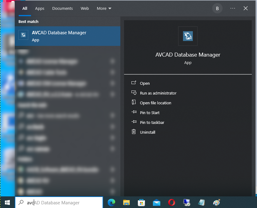
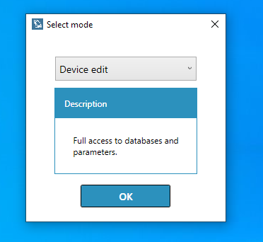
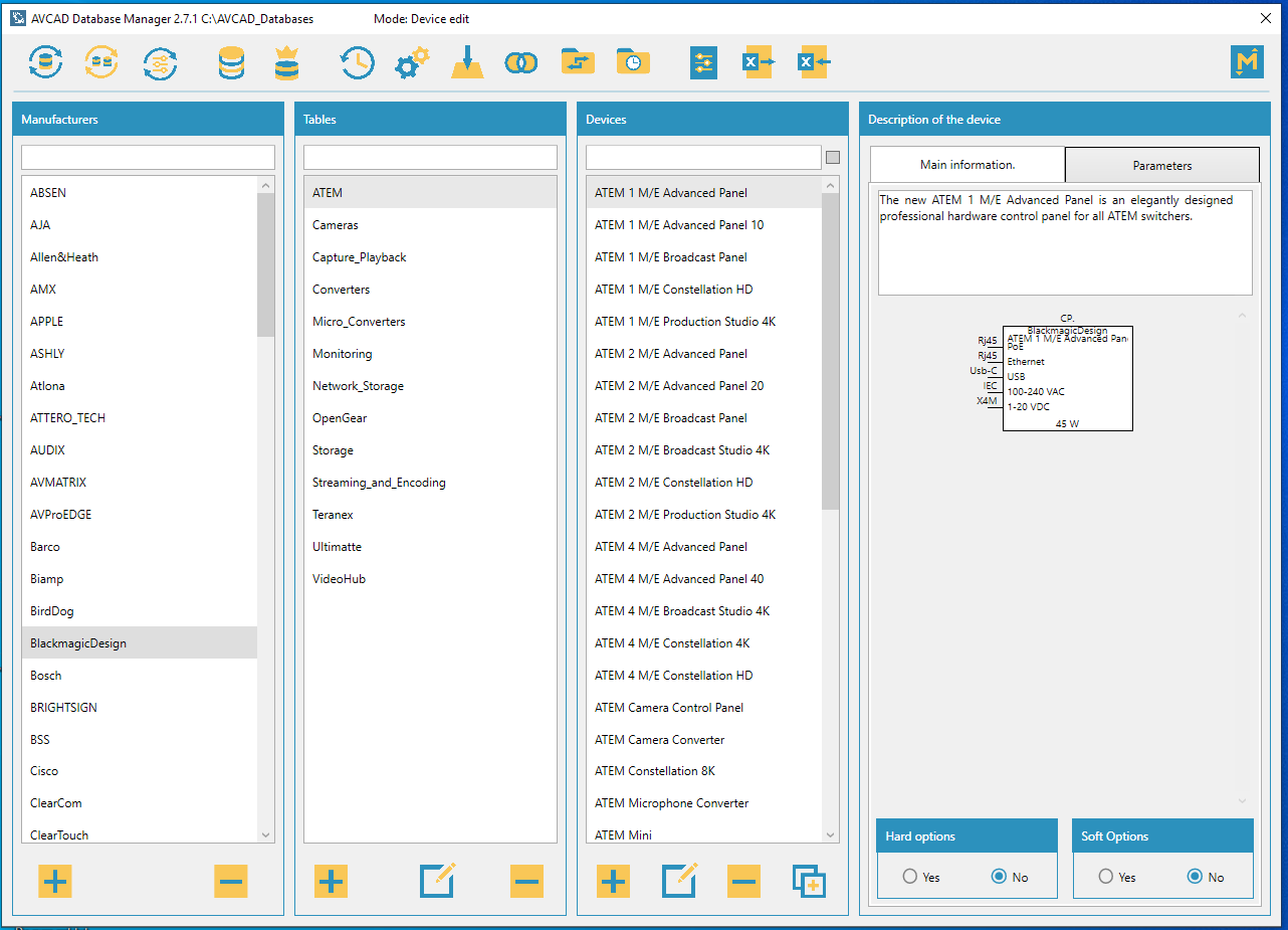
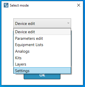
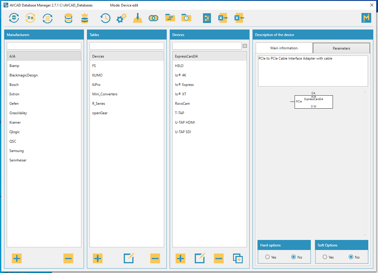
1.1.2. Launch the installation file and follow the instructions to complete the installation process. Launch AVCAD Database Manager. Choose Device Edit mode and click the OK button. The interface will appear.
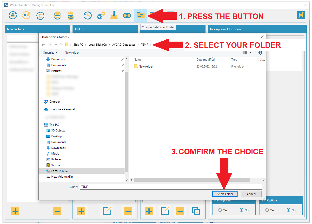
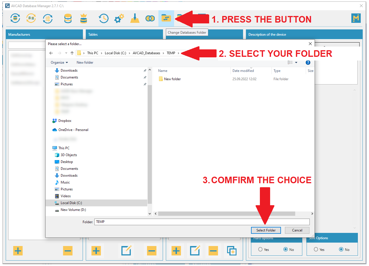
1.1.3. Click the Change Databases Folder button. Choose a folder for creating AVCAD databases (e.g., C:\AVCAD_Databases) or a shared folder if you want to share your databases with other users. Note: Use the shared folder if there are two or more AVCAD users. The shared folder needs to be mounted as a disk (e.g., C:\AVCAD_Databases).
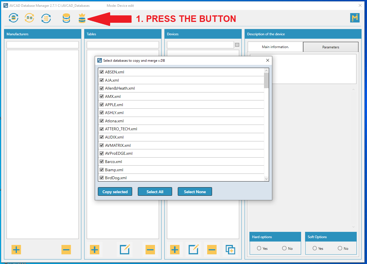
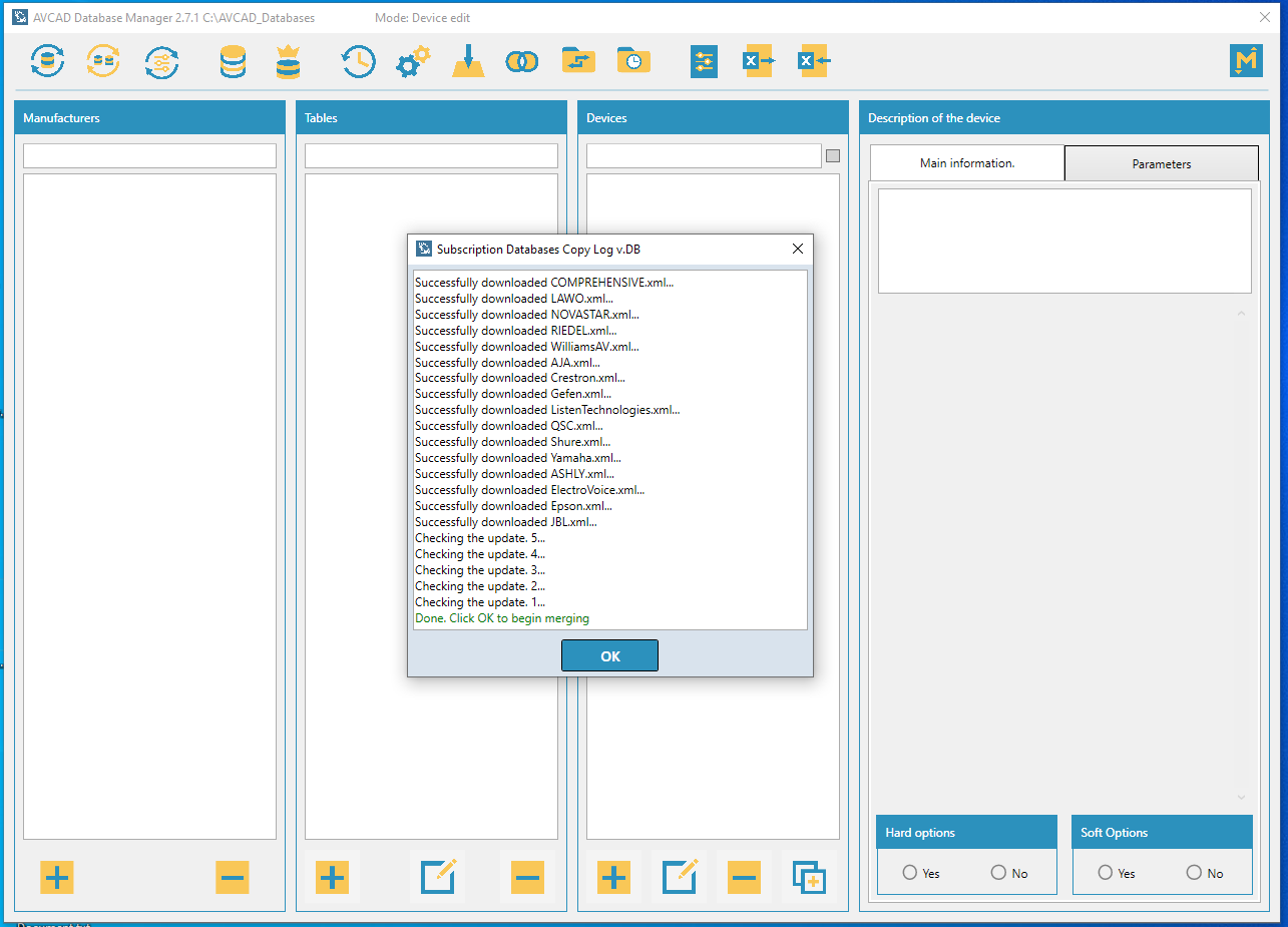
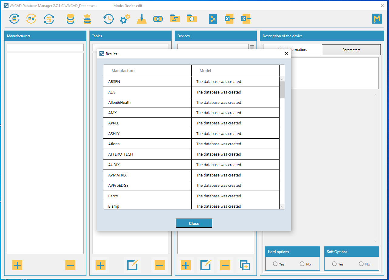
1.1.4a. If you have a Premium Databases license key, please activate it. Then click the Premium Databases button to download databases. Follow the instructions to complete the download. You will see a List of Manufacturers as a result.
Please, watch this video to see how it works: DATABASES
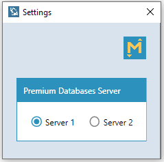
Note: Using Settings mode, users can change the cloud server with databases.
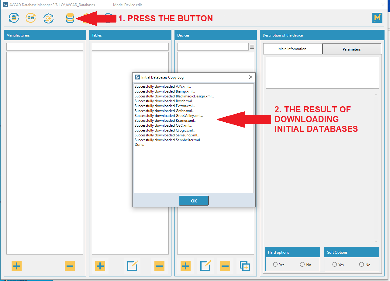
1.1.4b. If you are using the trial version of AVCAD or do not have a Premium Databases subscription, click the Initial Databases button to download free databases. Follow the instructions to complete the download. You will see a List of Manufacturers as a result.
1.2. Installation of AVCAD for Visio
1.2.1. Dowload the AVCAD installation file.
1.2.2. Launch the installation file and follow the instructions to complete the installation process.
1.2.3. Launch your Visio program. You should see the AVCAD commands in the Home ribbon.
Note: If you do not see AVCAD commands try to launch C:\Program Files (x86)\AVCAD V – AVCAD for Microsoft Visio\AVCAD-V.vsto manually. If you still do not see the AVCAD commands, remove all files from C:\Users\User\AppData\Local\Apps. Please note that User in the path refers to your Windows username, and the AppData folder may be hidden. After that try to launch vsto file again.
1.2.4a. If you want to use the free demo of AVCAD for Visio, simply run the AADB command. The interface will appear, and you will have a 2-week free trial after the first launch.
1.2.4b. If you have an AVCAD for Visio license key, please activate it.
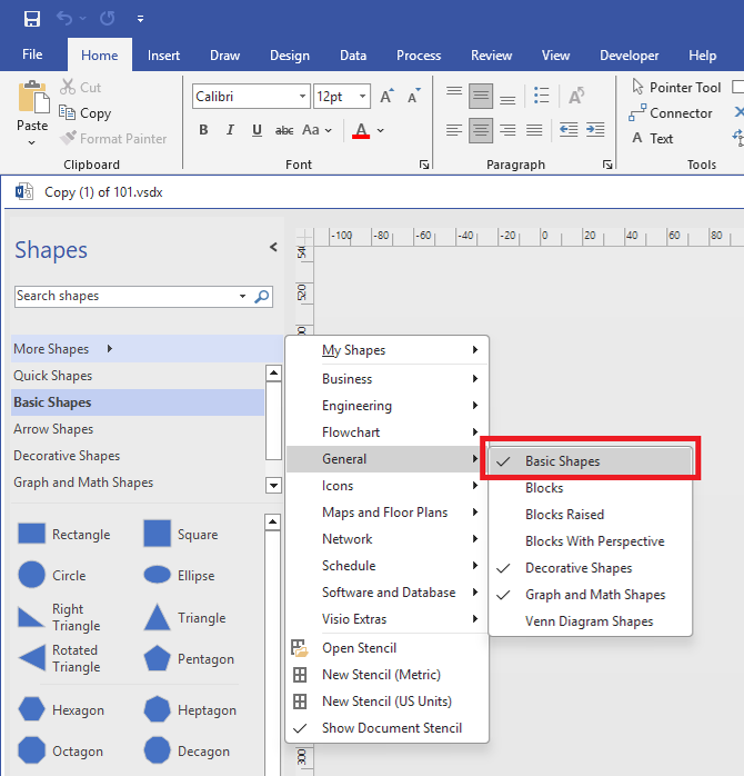
Note: Before you start working with AVCAD, make sure that Basic Shapes is enabled.
2. Import databases from AVCAD Database Manager to AVCAD
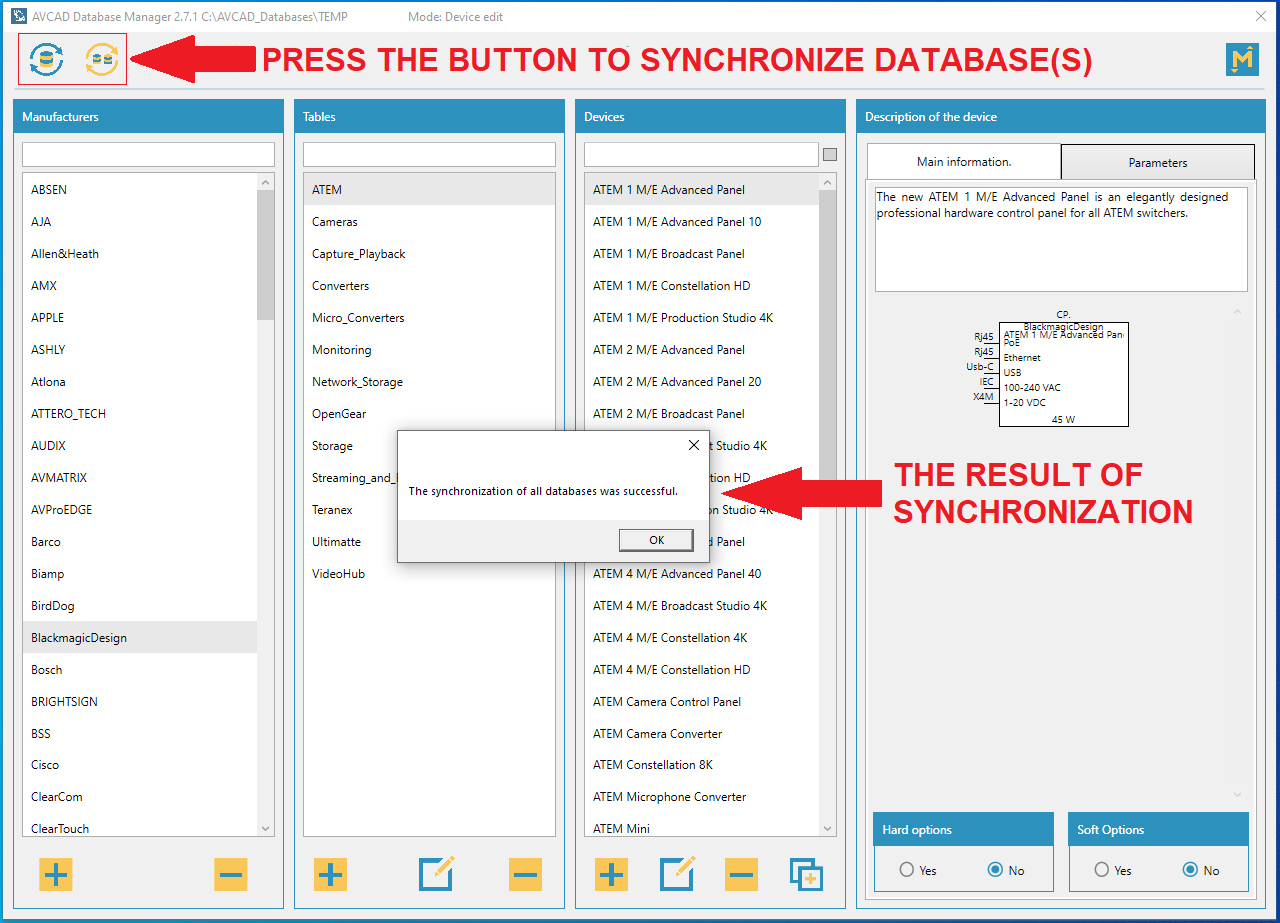
2.1. Open AVCAD Database Manager and choose Device Edit mode.
2.2. Use Synchronize the selected database or Synchronize all databases button to import database(s) from AVCAD Database Manager to AVCAD.
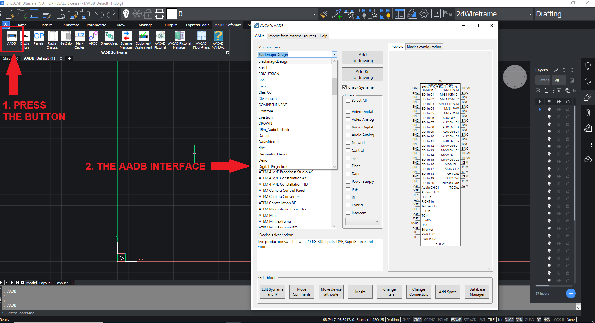
2.3. After that, run the AADB command in your Visio program. The interface will appear and you will see the list of Manufacturers.
3. Simple AVCAD drawing
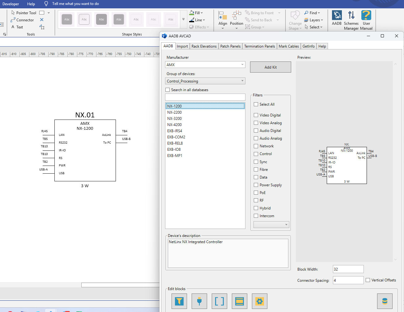
3.1. Adding devices to the Page (AADB command)
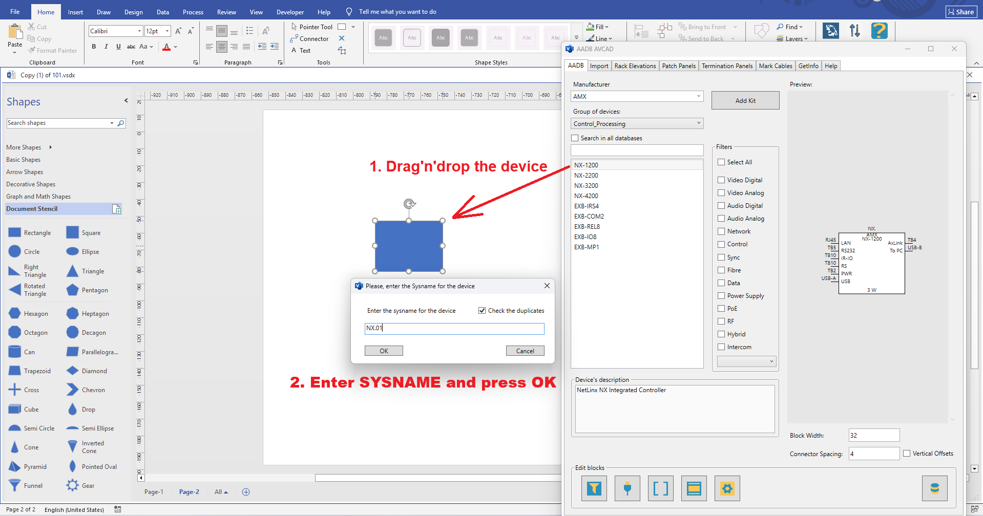
3.1.1. Run AADB command.
3.1.2. Choose Manufacturer.
3.1.3. Choose Group of devices.
3.1.4. Select Device.
3.1.5. Drop device using drag’n’drop gesture
Note: SYSNAME is the main id of a device into your drawing. The device can has many views (Visio’s shapes) and they all are linked with each other by the same SYSNAME. It is not allowed to have different devices with the same SYSNAME in the project.
3.1.6. Insert the block into the drawing. If device contains Hard Options choose them if needed. If device contains Options choose them if needed.
3.2. Add Patch or Termination Panel to the drawing
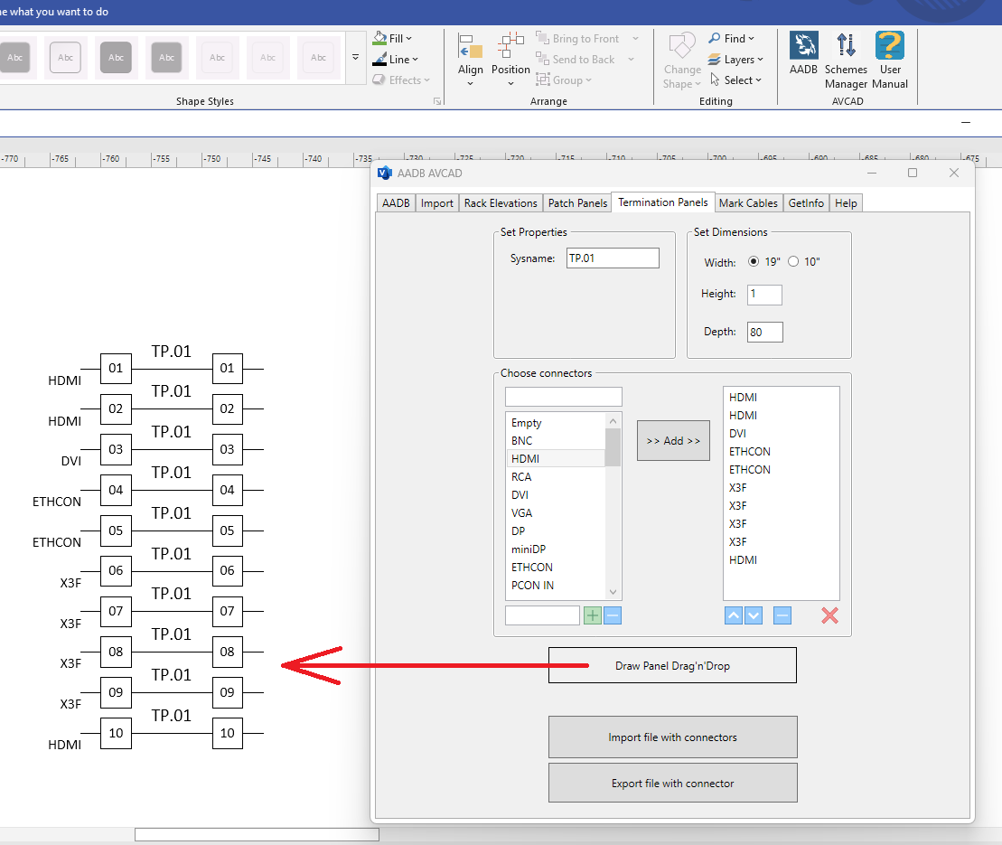
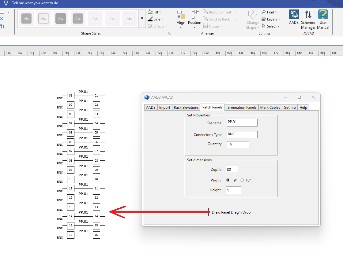
3.2.1. Run AADB->Patch Panels or AADB->Termination Panels command.
3.2.2. Type Sysname.
3.2.3.Type or choose needed connectors.
3.2.4. Add the panel to the drawing using drag’n’drop gesture.
3.5. Draw Rack layouts
3.5.1. Run AADB->Rack Elevations command.
3.5.2. Fill the form.
3.5.3.Draw views of the rack using drag’n’drop gestures.
3.5.4. Insert a device into Rack (Use Place Device to a Rack command). LOCATION attribute will be filled automatically.
Watch this video to understand how it works – DrawRack
Watch this video to understand how it works – FillRack